Underwater Science: Supercavitation, Bathymetry, & Acoustic Positioning

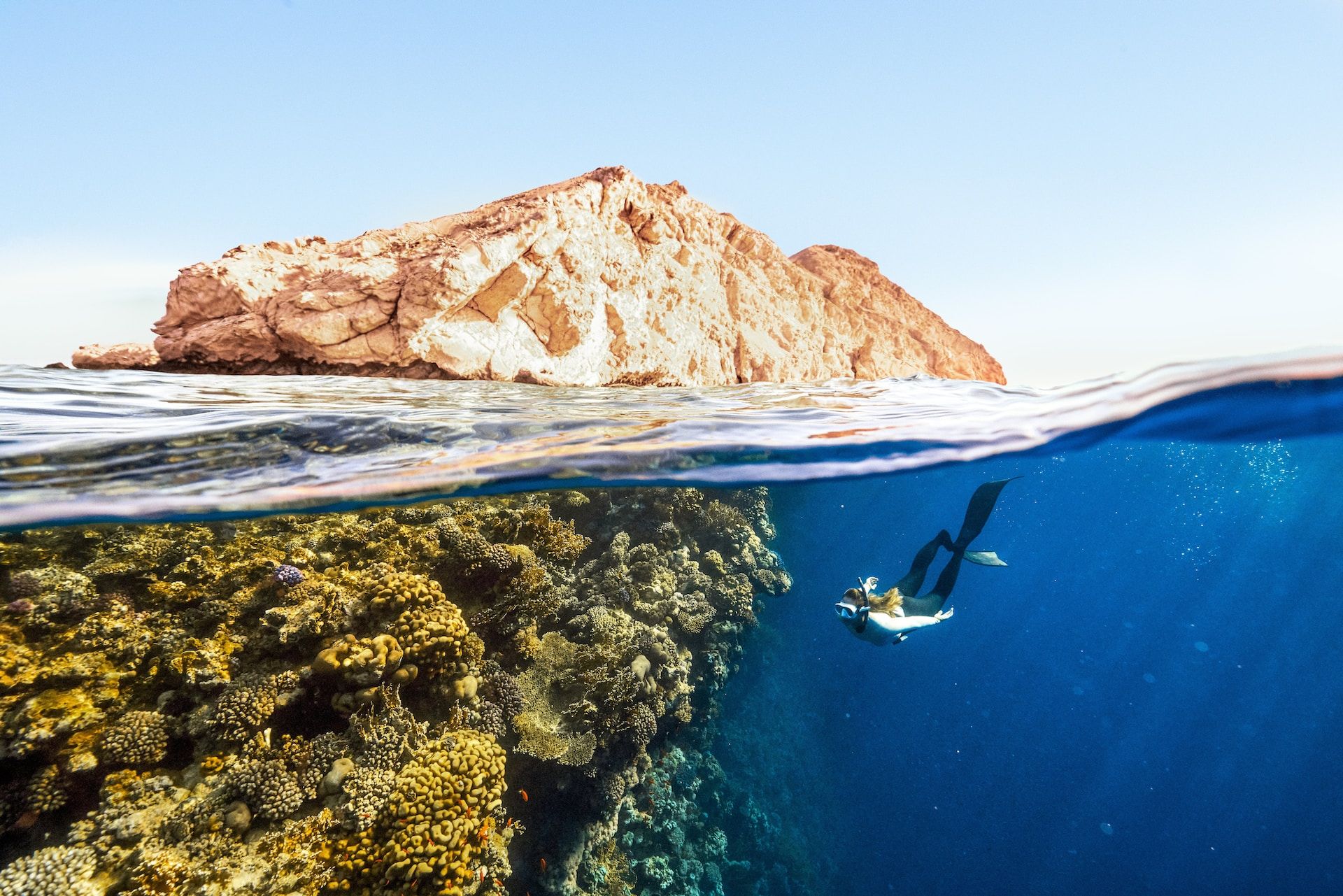
Space, space, and more space. Yet the least explored or mapped part of our world is what is underneath us within the great waters of the seas. Seventy per cent of the planet's surface is virtually unknown, and we can only move through it at the speed of a fast scooter. All earthly problems are fundamentally problems of physics.
Supercavitation: Can We Create A Supersonic Submarine Vehicle?
Drag is not the same in water as it is in air, obviously. And jet engines don't work underwater. Most modern nuclear-powered submarines can travel at speeds up to 25-35 knots (around 29-40 mph or 46-64 km/h) underwater. Commercial submarine speed is typically in the range of 2-3 knots (around 2-3.5 mph or 3.2-5.6 km/h), and drones have a maximum speed of around 4-6 knots (around 4.6-6.9 mph or 7.4-11.1 km/h).
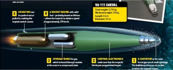
The fastest speed traveled underwater was by a supercavitating "carrier killer" torpedo, the Russian VA-111 Shkval ("squall"), which was developed during the 1960s at the Research Institute of Applied Hydromechanics and reached speeds of 200 knots, or around 230 mph (370 km/h): https://en.wikipedia.org/wiki/VA-111_Shkval
Further reading: https://web.archive.org/web/20120118040021/http://www.militaryperiscope.com/mdb-smpl/weapons/minetorp/torpedo/w0004768.shtml
In air, the speed of sound is about 343 meters per second, or 767 miles per hour (1,235 kilometers per hour), at sea level and at a temperature of 20 degrees Celsius. However, sound travels faster in water than in air. In seawater, the speed of sound is about 1,500 meters per second, or about 3,355 miles per hour (5,400 kilometers per hour).
Supersonic in water means Mach 4.37 in air.
Developments in supercavitation technology could enable better control and maneuverability of high-speed underwater vehicles. This could involve using advanced materials, fluid dynamics, and active control systems.
High-powered lasers or other energy sources could create a plasma field in the water around an underwater vehicle, where it may be possible to decrease drag and increase propulsion efficiency. Advances in material science (morphable materials) could allow underwater vehicles to change their shape dynamically, adapting to the water flow and reducing drag. This could involve the use of soft robotics or smart materials that change shape in response to external stimuli.
Including supercavitation, there are four current and proposed methods of underwater propulsion:
Conventional Propellers
Traditional underwater vehicles like submarines and remotely operated vehicles (ROVs) use propellers to generate thrust.
However, this method is not suitable for achieving supersonic speeds due to cavitation, a phenomenon that limits propeller efficiency and produces noise and vibrations.
Magnetohydrodynamic (MHD) Propulsion
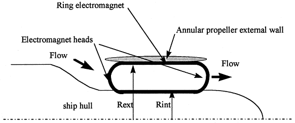
Electric and magnetic fields accelerate a conductive fluid, creating thrust.
- Water as fuel: Water around the object (such as a boat) is used as the "fuel." Because seawater has salt in it, it can conduct electricity.
- Electricity and magnetism: An electric current is sent through the water, and at the same time, a magnetic field is applied. When the electric current meets the magnetic field, it creates a force that pushes the water out of the way.
- Force creates motion: This force pushes the water backward, and due to Newton's third law ("for every action, there is an equal and opposite reaction"), the object (boat or submarine) is pushed forward.
Lorentz force: https://en.wikipedia.org/wiki/Lorentz_force
Although MHD propulsion allows for a quiet and efficient operation, it has not yet reached the stage of practical application in underwater vehicles.
"Introduction to Magnetohydrodynamics" (2017)
https://lweb.cfa.harvard.edu/~namurphy/Presentations/Murphy_MHD_2017.pdf
"Magnetohydrodynamic Submarine Propulsion Systems" (1991): https://onlinelibrary.wiley.com/doi/epdf/10.1111/j.1559-3584.1991.tb00945.x
Water Jet (Pump-jet, Hydrojet) Propulsion
Drawing water into a vessel and expelling it at high pressure to generate thrust. Water jets are used in some high-speed watercraft and ROVs. However, they have not yet been utilized for supersonic speeds.
More: https://en.wikipedia.org/wiki/Pump-jet
"A Review of Practical Water-Jet Propulsion" (1972): https://www.sae.org/publications/technical-papers/content/720278/
Supercavitation: the gas bubble
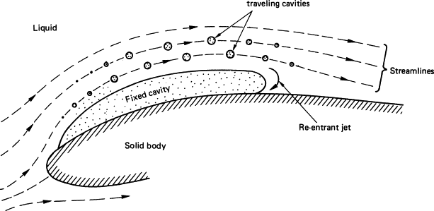
Supercavitation is a technique used to reduce drag on underwater objects, like torpedoes or submarines, allowing them to travel at high speeds. In simple terms, supercavitation works by creating a large bubble of gas around the object, which reduces contact with water and decreases resistance.
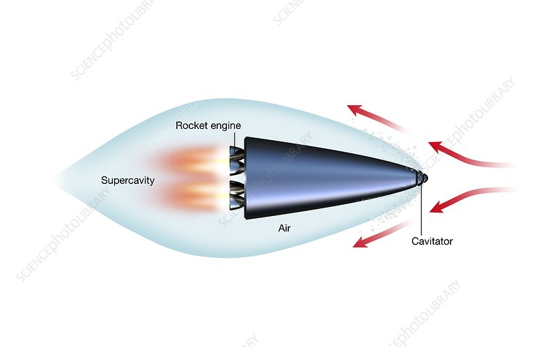
- Object shape: The underwater object has a specially designed shape, often with a sharp nose, to help generate supercavitation. This shape pushes water out of the way as the object moves, creating an area of low pressure at the front.
- Gas bubble creation: As the object moves through water, the low-pressure area at the front causes the water to vaporize, creating a gas bubble (also known as a cavity). In some cases, gas (like air or exhaust gases) is also injected to help form and maintain the bubble.
- Bubble envelops the object: The gas bubble expands and envelops the object, significantly reducing the contact between the object's surface and the water. This reduces drag, or water resistance, allowing the object to travel much faster than it could otherwise.
- Maintaining the bubble: To keep the bubble stable and prevent it from collapsing, gas needs to be continuously added, either by the object's forward motion or through an additional gas injection system.
However, it has one major drawback which has yet to be solved.
The U.S. military has long been interested in building a super-speedy submarine. A decade ago, DARPA tinkered with the idea of an experimental supercavitation sub, the Underwater Express, to carry troops underwater at more than 115 mph. But it faced a fundamental problem: Rocketing along inside its bubble, such a vehicle would have no way to steer itself. Now the Chinese are working on a concept that could overcome that hurdle. Scientists at Harbin Institute of Technology’s Complex Flow and Heat Transfer Lab have developed a liquid membrane that could be used to help steer a sub at high speed. This approach could open the door, they say, to a supersonic sub that could cover the 6,000 miles from Shanghai to San Francisco in 100 minutes.
"Supersonic Underwater Travel May Be Coming Soon" (2016)
https://nymag.com/speed/2016/12/supersonic-underwater-travel-may-be-coming-soon.html
https://time.com/3180108/travel-transportation-transport-supercavitation-supersonic-submarine-harbin-institute-of-technology-li-fengchen/
Steering a supercavitating submarine vehicle presents challenges due to the reduced contact with water and the high speeds involved. However, several current and theoretical approaches can be used to control and maneuver these vehicles:
- Control surfaces within the cavity: One approach to steering a supercavitating vehicle is to use control surfaces, such as fins or rudders, that are located within the gas cavity. These control surfaces would still have contact with the water-gas mixture inside the cavity, allowing them to generate forces for maneuvering. However, this method might be less effective than in conventional underwater vehicles due to the reduced water contact.
- Control surfaces outside the cavity: Another approach involves using control surfaces that extend outside the gas cavity, making direct contact with the water. By adjusting the angle and position of these control surfaces, the vehicle can change its direction. However, this method could increase drag and negatively impact the vehicle's speed and efficiency.
- Thrust vectoring: Thrust vectoring involves changing the direction of the propulsion force to control the vehicle's movement. For example, a supercavitating vehicle with rocket or jet propulsion could use thrust vectoring by redirecting the exhaust gases to steer the vehicle. This approach avoids the need for control surfaces in contact with water, potentially maintaining high speeds and efficiency.
- Pulsed gas injection: In this theoretical approach, the vehicle would use a system of adjustable gas injectors to control its movement. By varying the amount and direction of gas injected into the cavity, the vehicle could generate asymmetric forces that help steer it. This method would not rely on control surfaces, potentially minimizing drag and maintaining high speeds.
- Variable cavitator geometry: Another theoretical approach involves dynamically changing the shape of the vehicle's nose or cavitator to alter the gas cavity's shape and size. By adjusting the cavitator geometry, the vehicle could generate asymmetric forces on the gas cavity, enabling it to change direction.
Current and theoretical approaches involve using control surfaces within or outside the gas cavity, thrust vectoring, pulsed gas injection, and variable cavitator geometry. Each method has its advantages and drawbacks, and further research and development are required to optimize steering and control in supercavitating vehicles.
"Warp Drive underwater" (Scientific American): https://www.jstor.org/stable/26059211
"Supercavitation and aerospace technology in the development of high-speed underwater vehicles." (2003): https://www.researchgate.net/publication/268565242_Supercavitation_and_Aerospace_Technology_in_the_Development_of_High-Speed_Underwater_Vehicles
Could We Combine Magnetohydrodynamism & Supercavitation?
Combining Magnetohydrodynamic (MHD) Propulsion and supercavitation technologies could potentially lead to ultra-high-speed underwater propulsion systems. As a recap:
- MHD propulsion uses electric and magnetic fields to accelerate a conductive fluid (usually seawater), creating thrust without moving parts. By passing seawater through an MHD duct, an electric current is induced in the water, and magnetic fields are applied perpendicular to the current. The interaction between the current and magnetic fields generates a force (Lorentz force) that propels the vehicle forward.
- Supercavitation involves the creation of a gas bubble (cavity) around an underwater vehicle, significantly reducing drag by minimizing contact between the vehicle's surface and the water. The cavity is typically created by injecting gas (e.g., air or exhaust gases) at the vehicle's nose or by using specially designed shapes (cavitators) that generate a low-pressure area, causing the water to vaporize.
A combined MHD and supercavitation propulsion system might look something like this:
- Cavitator Design: The underwater vehicle could feature a specially designed nose or cavitator that creates a low-pressure area, initiating the formation of a gas cavity around the vehicle. This would reduce hydrodynamic drag and minimize the energy required for propulsion.
- MHD Duct Placement: MHD ducts could be strategically placed along the vehicle's hull, within the gas cavity. The electric current and magnetic fields generated in the MHD ducts would accelerate the gas-seawater mixture within the cavity, creating thrust and propelling the vehicle forward.
- Gas Injection: To maintain the gas cavity and ensure stable supercavitation, a controlled gas injection system could be incorporated. This system would continuously inject gas (e.g., air or exhaust gases) into the cavity, compensating for the gas that is lost due to diffusion or turbulence.
- Control and Maneuverability: To enhance maneuverability and control at ultra-high speeds, additional MHD ducts or control surfaces could be integrated into the vehicle's design. By varying the current and magnetic fields in these ducts, the vehicle could alter the force distribution and achieve more precise control of its movements.
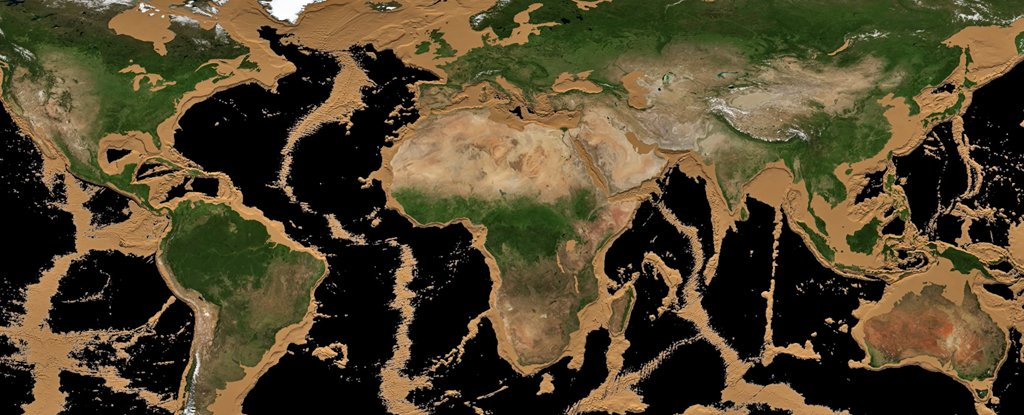
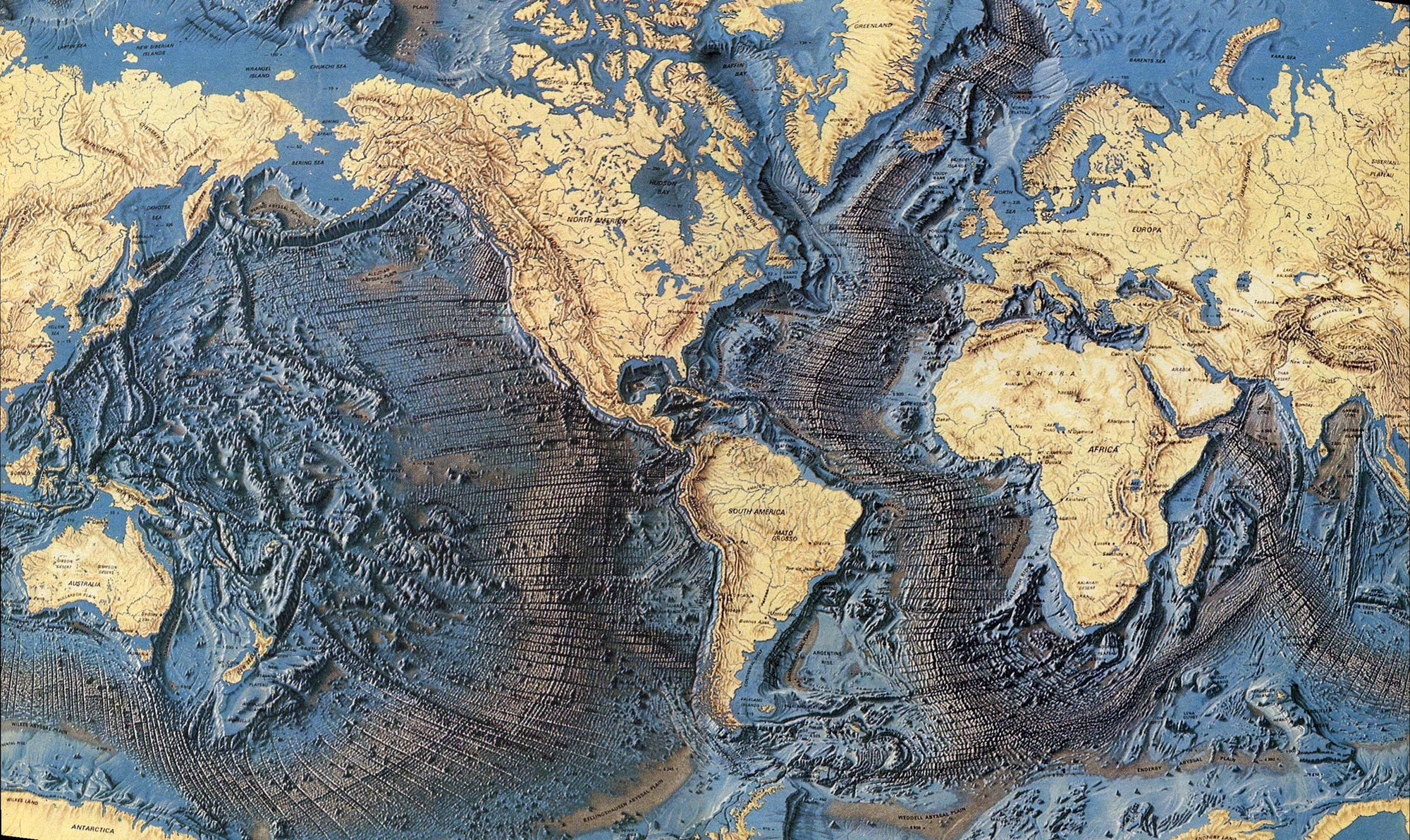
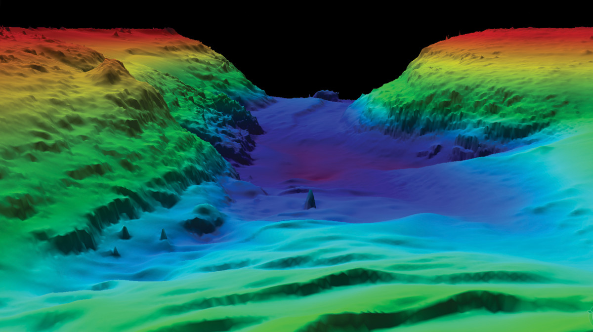
Bathymetry Scanning: Can We Create A Map Of The Ocean Floor?
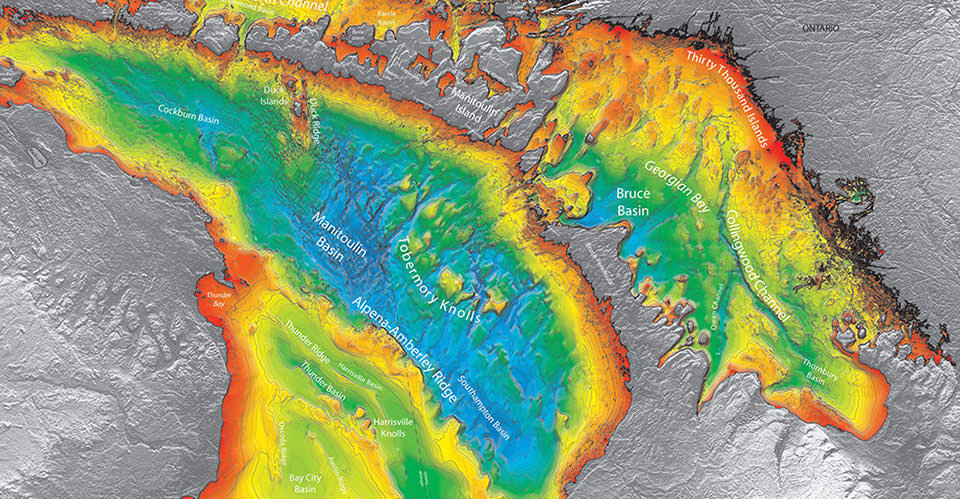
Topography is the study of the forms and features of land surfaces. The undersea equivalent is "submarine topography" or bathymetry.
Bathymetry is the measurement of the depth of water in oceans, rivers, or lakes. Bathymetric maps look a lot like topographic maps, which use lines to show the shape and elevation of land features. On topographic maps, the lines connect points of equal elevation. On bathymetric maps, they connect points of equal depth. A circular shape with increasingly smaller circles inside of it can indicate an ocean trench. It can also indicate a seamount, or underwater mountain.
https://education.nationalgeographic.org/resource/bathymetry/
Underwater terrain mapping involves measuring and characterizing the depth and features of the seafloor.
Echo Sounding
Echo sounders, also known as depth sounders or sonar systems, are the most common tools for mapping underwater terrain. They emit sound pulses (pings) into the water, which bounce off the seafloor and return to the sensor. The time it takes for the sound to travel to the seafloor and back is used to calculate the water depth. Single-beam and multibeam echo sounders are the two main types:
a. Single-beam Echo Sounders: These emit a single sound pulse vertically downward and provide depth information directly below the vessel. They are suitable for small-scale surveys and simple mapping tasks.
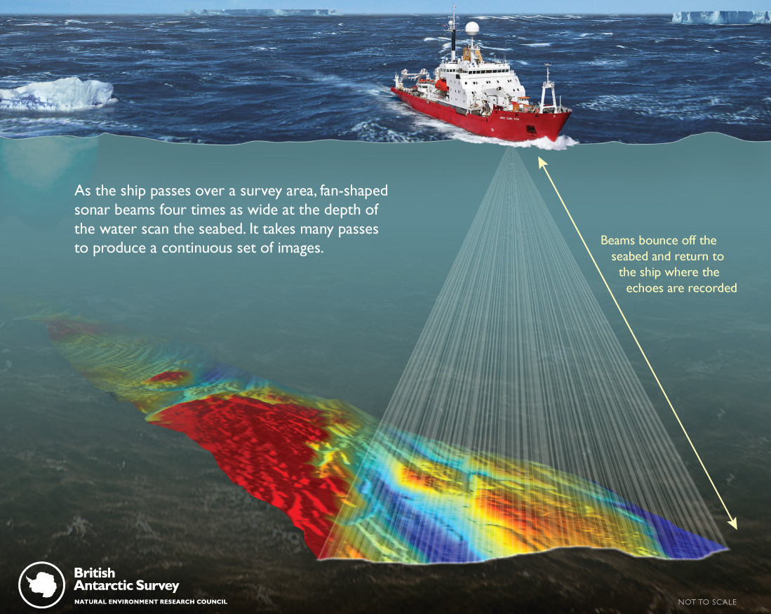
b. Multibeam Echo Sounders: These systems emit multiple sound pulses simultaneously at various angles, providing a wide swath of depth data. They enable more detailed and accurate mapping of underwater terrain, as well as coverage of larger areas.
c. Synthetic-Aperture Sonar (SAS): This combines a number of acoustic pings to form an image with much higher along-track resolution than conventional sonars.
https://en.wikipedia.org/wiki/Multibeam_echosounder
Side-Scan Sonar
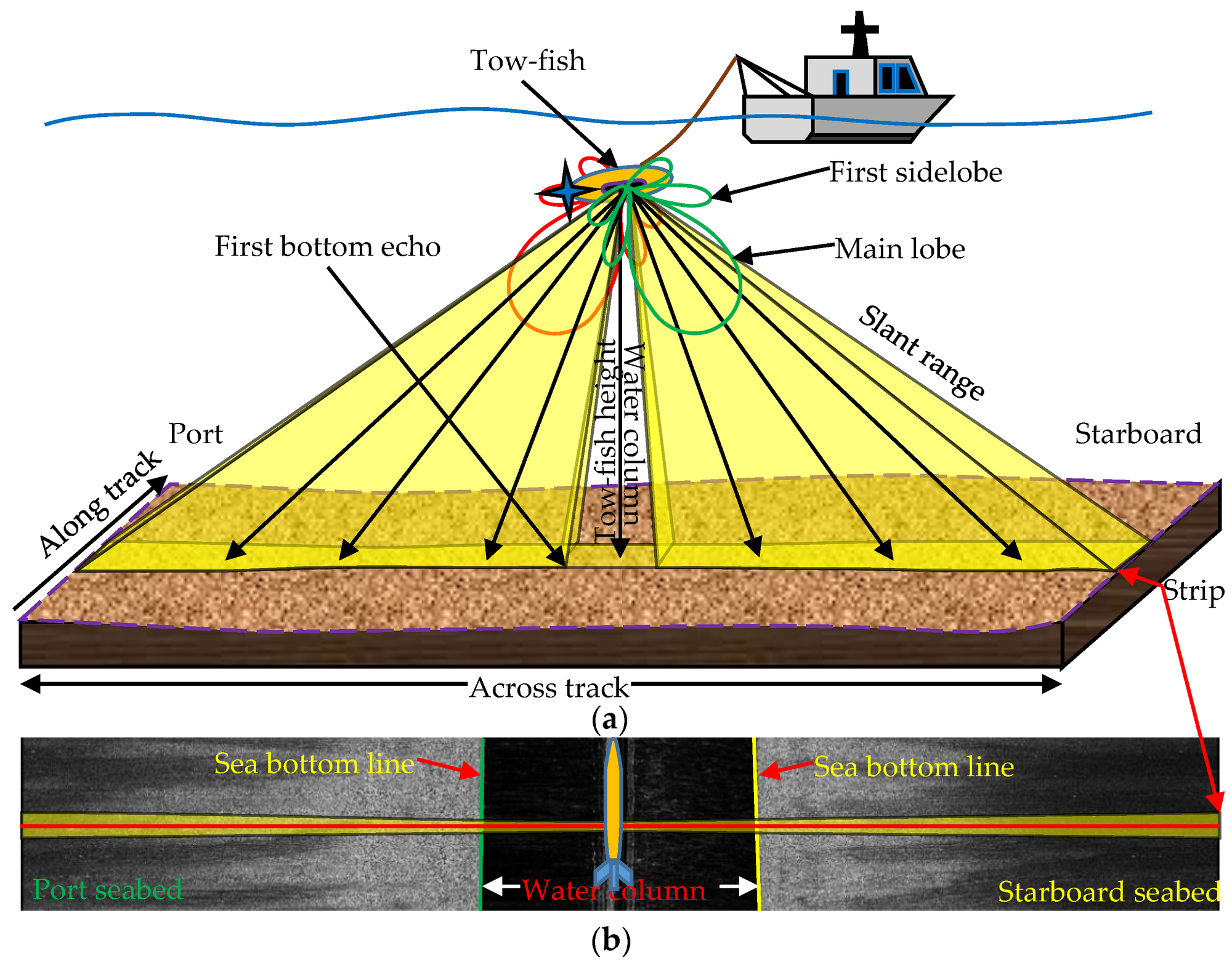
Side-scan sonar systems emit sound pulses horizontally and capture the reflected sound off the seafloor. This method provides high-resolution images of the seafloor and helps identify underwater features, such as shipwrecks, rocks, and vegetation. However, it does not provide direct depth measurements like echo sounders.
https://en.wikipedia.org/wiki/Side-scan_sonar
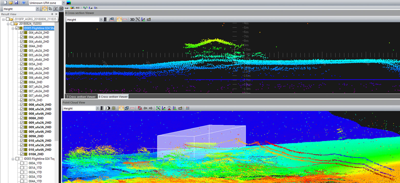
LiDAR (Light Detection and Ranging)
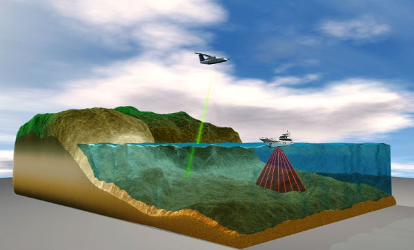
Airborne LiDAR systems use laser pulses to measure the distance from the aircraft to the seafloor. The laser pulses penetrate the water surface and reflect off the seafloor back to the sensor. LiDAR is effective in mapping shallow coastal areas and provides high-resolution bathymetric data. However, its effectiveness decreases with increasing water depth and turbidity.
https://www.hydro-international.com/themes/bathymetric-lidar
Satellite Remote Sensing
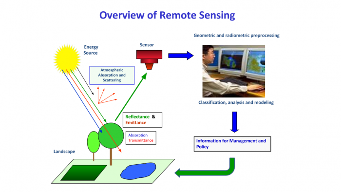
Satellite-based methods use radar altimetry and multispectral imaging to estimate water depth and seafloor features. These methods are useful for mapping large areas of the ocean, but they offer lower resolution and accuracy compared to echo sounders and LiDAR.
Drones
AUVs and ROVs are unmanned underwater vehicles equipped with various sensors, including echo sounders, side-scan sonar, and cameras. They can be deployed for detailed and high-resolution mapping of the seafloor, especially in challenging environments like deep-sea trenches and hydrothermal vents.
Understanding EM sources
In theory, certain forms of electromagnetic (EM) radiation have different viabilities for underwater applications as an alternative to sound/sonar.
- Light Detection and Ranging (LiDAR) is used in airborne and terrestrial applications for mapping and is starting to see use in shallow water bathymetry. However, its potential for deep-water bathymetry is limited due to the rapid absorption and scattering of light in water. Infrared radiation has similar limitations, with even stronger absorption.
- Low-frequency radio waves are typically used for communication rather than imaging, but they can penetrate water to some degree. The exact depth to which they can penetrate depends on the frequency, with lower frequencies penetrating deeper. For instance, submarines use Very Low Frequency (VLF) or Extremely Low Frequency (ELF) radio waves for communication when submerged. However, these frequencies have very long wavelengths, which means they would provide very low resolution if used for imaging. This makes them unsuitable for most bathymetric applications.
- X-rays and Gamma Rays are highly penetrative and can pass through water. However, their use in a bathymetric context is not practical due to safety considerations and technical challenges. Moreover, they would be strongly absorbed by the water, which would limit their range.
Long Baseline Acoustic Positioning: Can We Create An Underwater GPS?
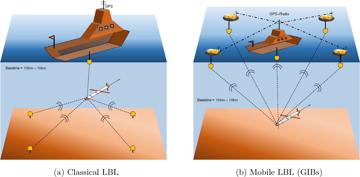
Long baseline (LBL) acoustic positioning is already a well-established technique for underwater navigation. It involves using a network of transponders (also called beacons) anchored to the seafloor, which communicate with a transceiver on the vessel or autonomous underwater vehicle (AUV). The system works by measuring the time it takes for an acoustic signal to travel between the transponder and the transceiver, which allows the determination of distance.
The position of each transponder is known, and one of the transponders is usually chosen as the origin of the coordinate system (0,0,0). The positions of the other transponders are then defined in terms of x, y, and z Cartesian coordinates relative to this origin.
Adapting & Scaling LBL
To create a wide-scale LBL system for underwater navigation it would need modifications and extensions:
- Network of Transponders: The ocean floor would need to be populated with a dense grid of transponders, with overlapping coverage to allow for continuous navigation. These devices would need to be robust to withstand the pressures and conditions found at the ocean floor.
- Adapting to Ocean Topography: The positioning of transponders would have to account for the varying topography of the sea, including deep trenches, underwater mountains, and ridges. The transponders would be positioned at varying heights on flexible tethers, allowing them to adjust to changing seabed conditions.
- Signal Processing: Advanced signal processing methods would be required to address issues like multipath propagation (where signals bounce off the seafloor and sea surface), signal attenuation, and variations in sound speed due to changes in water temperature, pressure, and salinity.
- Redundancy and Error Correction: To increase the reliability of the system, redundancy would have to be built in. This could involve having multiple transponders within range of a given point, allowing for error-checking and correction. Machine learning algorithms could be used to optimize these error correction methods.
- Maintenance and Powering: The transponders will need to be periodically serviced and powered. Given the vastness of the sea, solar-powered surface buoys tethered to the transponders could be used. The buoys could house batteries and electronics for charging the transponders and performing surface communications.
- Surface Communication: The system would need a method for communicating with surface vessels and land-based stations. This could involve satellite uplinks on the surface buoys, allowing for real-time tracking and control of underwater vehicles.
- Dynamic Positioning: Given the varying currents and conditions within the Atlantic, underwater vehicles using the system will need to have dynamic positioning capabilities. This would allow them to maintain a fixed position despite the ocean's movement.
Building in GPS features: Using buoys
Being analogous to GPS would be a significant challenge due to the properties of water that make it difficult for radio waves to propagate, especially over large distances. GPS signals can't penetrate very far into water due to its high absorption.
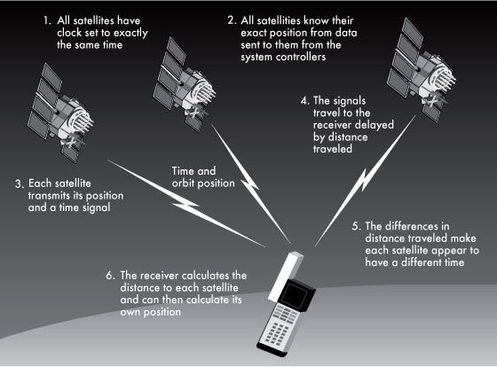
- Acoustic Signaling: Underwater GPS could use an array of stationary, anchored buoys throughout the ocean, each equipped with a sonar transmitter and receiver. These buoys would continuously send out sonar pings, which could be received by underwater vehicles or devices.
- Time of Flight (ToF) Measurements: The underwater vehicle or device could have an onboard sonar system that could receive these pings. By timing how long it takes for the sonar signal to reach it from each buoy, the device could calculate its distance from each buoy.
- Triangulation: Just like with GPS, the device could then triangulate its position by comparing the distances to at least three buoys. This would give it a 3D position fix under the sea.
- Communication: The buoys themselves could be connected to each other and to the surface using fiber optic cables or even a radio relay system when they are above the water surface. This way, they could receive updates from a central system, synchronize their pings, and relay information about the underwater vehicles or devices back to the central system.
However, there are problems to overcome.
- Depth Variations and Signal Attenuation: The speed of sound in water varies with temperature, salinity, and pressure (which changes with depth). These variations can result in signal bending and attenuation, complicating the time of flight calculations.
- Seafloor Topography: Mountainous or uneven seafloor can obstruct the sonar signals. This means our underwater GPS might not work as well in some parts of the ocean as others (see question befor this).
- Signal Interference: Marine life and human activities can generate noise that interferes with the sonar signals.
- Logistics and Costs: Installing and maintaining a global network of buoys would be a significant undertaking. Each buoy would need to be anchored to the seafloor and regularly maintained to ensure it's working correctly.
Linking wide-scale LBL to WGS84 GPS
Could we go one step further and link an "underwater GPS" system to the original atmospheric GPS system to create a universal positioning system?
To connect an LBL system to GPS, you need to know the GPS coordinates of each transponder on the seafloor. And they move around a lot.
- Deployment: When the transponders are initially deployed from a surface ship, their positions are marked using GPS. This can be done to a high degree of accuracy, but it requires calm sea conditions and careful deployment procedures.
- GPS-Acoustic Systems: For even greater accuracy, a GPS-Acoustic (GPS-A) system can be used. This involves placing a transponder on the seafloor and a GPS receiver on a buoy or surface ship directly above it. The GPS receiver provides a precise position on the surface, and the distance to the transponder is measured acoustically. By combining the GPS and acoustic data, the transponder's position can be calculated with high precision.
- Transponder Position Updates: Over time, transponders can move due to currents, seismic activity, or other factors. To account for this, their positions can be periodically updated. This is usually done by performing a GPS-Acoustic survey, as described above.
Once the GPS coordinates of the transponders are known, the LBL system can be considered as connected to the GPS. This means that an underwater vehicle or instrument can determine not only its position relative to the LBL transponders but also its absolute position in GPS coordinates.
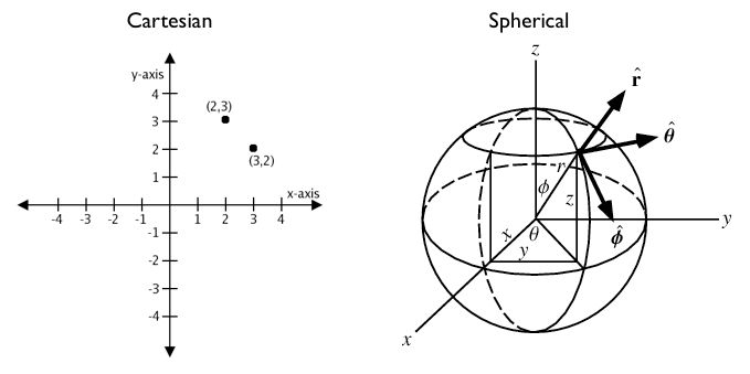
More on 3D coordinates: https://www.usna.edu/Users/oceano/raylee/SM223/Ch12_1_Stewart(2016).pdf
Can We "See" Into The Water Below Like Radar?
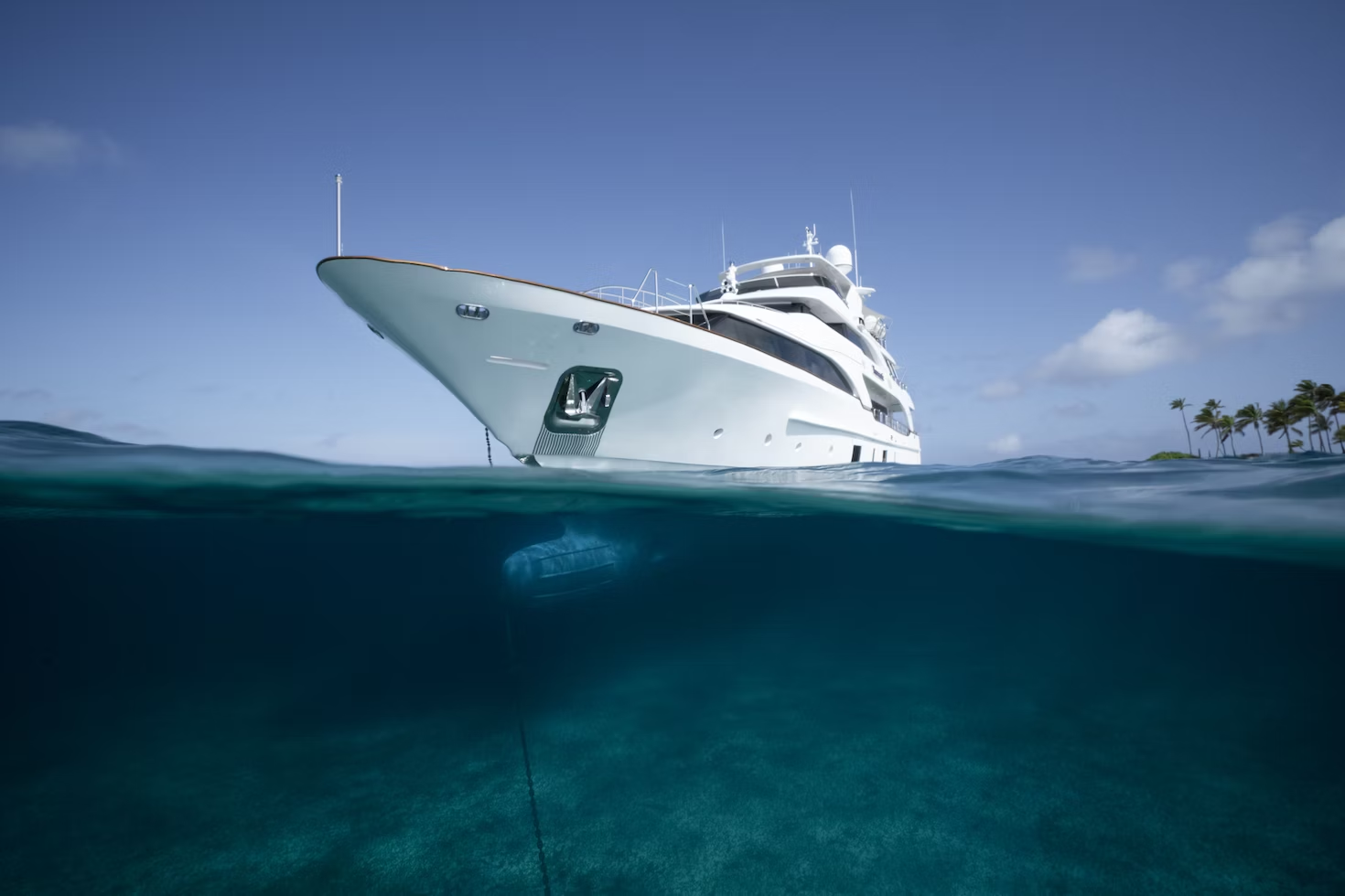
This is obviously related to scanning the seabed, but more in tune with how a Tesla "sees" or "senses" the road ahead using known imagery. If a vehicle knows its position, can it call up imagery of the water below and recreate it in 3D, or could it "see" directly below to any distance?
The simple answer is: kinda. We can use lasers in shallow water, but they need power. For deeper water, we rely on sound. The workaround is underwater drones, which can determine their own position and have onboard LiDAR for seabed scanning.
How far can LiDAR take us?
LiDAR technology is limited in its ability to penetrate water, especially at extreme depths. The effectiveness of LiDAR decreases as water depth increases, and it becomes less accurate and reliable. This limitation is primarily due to the absorption and scattering of light by water, suspended particles, and dissolved organic matter. In general, LiDAR is most effective for mapping shallow coastal areas and is not well-suited for deep-sea exploration.
For normal ships sailing in relatively shallow waters, such as in the Caribbean Sea, LiDAR can provide useful bathymetric data to some extent. However, the depth penetration and accuracy of LiDAR in these conditions will still be limited compared to other underwater mapping technologies like echo sounders or sonar systems.
In deep-sea environments, such as those encountered by submarines or low-depth research vessels, LiDAR is not a practical solution for underwater mapping. Instead, these vessels typically rely on sonar systems, specifically multibeam echo sounders and side-scan sonar, to map the seafloor and "see" the underwater terrain. These technologies use sound waves, which can travel much greater distances in water and provide more accurate depth measurements than light-based methods like LiDAR. Autonomous underwater vehicles (AUVs) and remotely operated vehicles (ROVs) can also be equipped with sonar systems and other sensors to conduct detailed, high-resolution mapping of deep-sea environments.
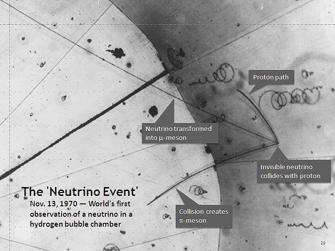
Mad science: could we use neutrinos?
A neutrino is a very tiny particle that's part of the universe's fundamental building blocks, much like electrons. But unlike electrons and other particles we're more familiar with, neutrinos have some unique properties.
- They're incredibly light: Neutrinos are among the lightest particles in the universe. They're so light, in fact, that scientists thought they were completely massless for a long time.
- They hardly interact with anything: Neutrinos are like the ghosts of the particle world. They can pass through solid matter almost as if it's not there. This is because they only interact through the weak force (one of the four fundamental forces of nature) and gravity, but not through the electromagnetic force. So, they don't bump into atoms like other particles do.
- They're neutral: Neutrinos carry no electric charge, which is why they're named neutrinos, meaning "little neutral ones" in Italian.
- They're produced in nuclear reactions: Neutrinos are produced in large quantities in the sun and other stars, in nuclear reactions and during supernovae. They're also produced in nuclear reactors on Earth and when cosmic rays hit the Earth's atmosphere.
- There are three types, or "flavors," of neutrinos: These are called the electron neutrino, muon neutrino, and tau neutrino. Fascinatingly, a neutrino can change from one type to another in a process called "neutrino oscillation."
They can pass through matter, including water, with minimal interaction, making them potentially suitable for deep-sea sensing applications.
In theory, a neutrino-based sensing system would emit a beam of neutrinos from a source, such as an underwater vehicle or research vessel. The neutrinos would then travel through the water and interact with the seafloor or other underwater features. By detecting and analyzing the neutrinos that are scattered or absorbed by the underwater environment, it might be possible to create detailed maps and gather information about the composition and structure of the seafloor.
However, you'd face some hurdles.
- Neutrino Generation: Generating a controlled beam of neutrinos would require a compact and efficient source. Existing neutrino sources, such as nuclear reactors and particle accelerators, are large and not suitable for underwater applications. They might be able to be derive them from small modular reactors found in submarines.
- Neutrino Detection: Detecting neutrinos is challenging due to their weak interactions with matter. Large and sensitive detectors are typically required to capture and analyze neutrino signals. Developing compact and efficient neutrino detectors would be essential for practical underwater applications.
- Data Processing and Analysis: Neutrino-based sensing would generate large amounts of data, requiring sophisticated processing and analysis techniques to extract meaningful information about the underwater environment.
- Energy Requirements: Generating and detecting neutrinos, as well as processing the data, would likely require significant amounts of energy. Developing compact and efficient energy sources for underwater vehicles would be crucial for the feasibility of neutrino-based sensing systems.
It's off-limits for now, but it's a wonderfully sci-fi thought.