An Arduino Wifi Racetrack For Remote Controlled Toy Cars & Boats

Why? Because inside every man is a six year-old waiting to re-emerge. Sometimes you don't need a reason for a project. You simply do it because its awesome level breaks the charts, and/or for no damned reason at all.
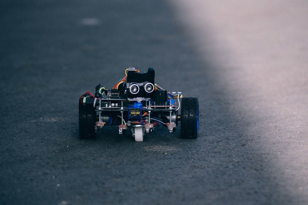
What if we could power this bad boy in a browser, over wifi?

Yes, you can buy Wifi-controlled toys off the shelf. But it's not as fun as building them, and you can't buy a whole racetrack which you can also connect to Wifi, analyze with motion detectors, mix video streams, and geometrically interrogate with Postgis spatial functions.
There are plenty of great tutorials out there for it too: –
- https://create.arduino.cc/projecthub/andriy-baranov/from-bt-to-wifi-creating-wifi-controlled-arduino-robot-car-09b7c1
- https://www.instructables.com/id/DIY-WIFI-RC-Car-With-ESP8266-and-Arduino-IDE/
Then, of course you don't just have drones and planes and cars, you have boats:
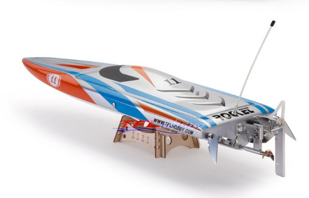
But why stop there? If you're going to do a boat, why not go big or go home? How about an AIRCRAFT CARRIER?
Aircraft carriers are hard to come by; particularly the remote controlled kind: https://www.popularmechanics.com/flight/drones/a18162/rc-aircraft-carrier-plane/
Models, however, are pretty easy to get, if a little expensive. But they don't have motors. Where else are you going to land your drone?
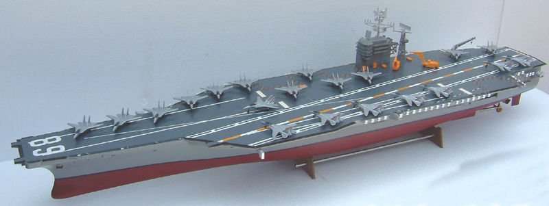
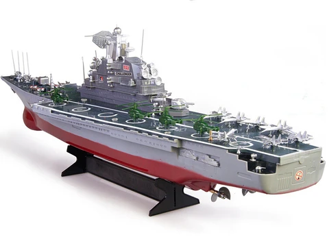
That's settled then. A fleet of Wifi-powered RC aircraft carriers. More on models: https://sdmodelmakers.com/naval-warship-models/aircraft-carrier-models/
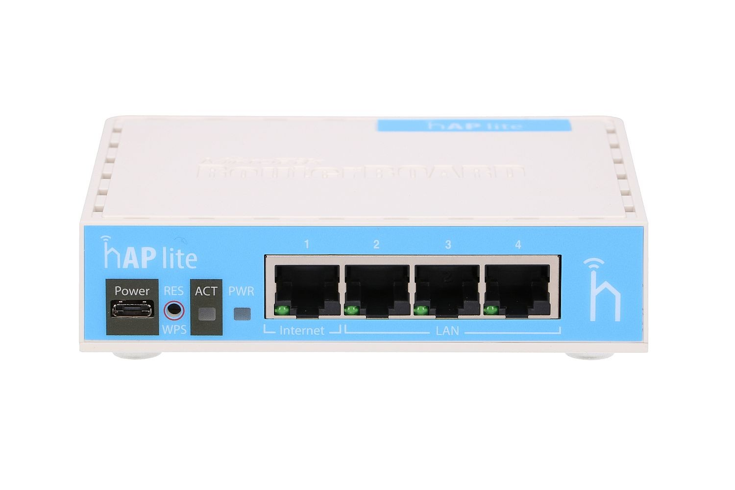
How Do You Set Up A Portable Wifi Network?
Well, most people can use their phones and create a hotspot. However, it's crude. Signal is crap and there's no control of the router, the ports, the settings etc.
Consider the following scenario: we are on a floating panel in the middle of a small lake in a remote local park and have 5 wifi-powered rubber ducks we want to race live on the Internet. For no reason.
We need a Wifi router with a good signal strength. But most of them have to be plugged into a) a residential power outlet, and b) an upstream Internet signal from a cable/DSL modem.
These things are crucial:
- Cheap
- Simple
- Reliable
- Strong signal
- Battery-powered
- 3/4G/LTE SIM card-powered
- Programmable
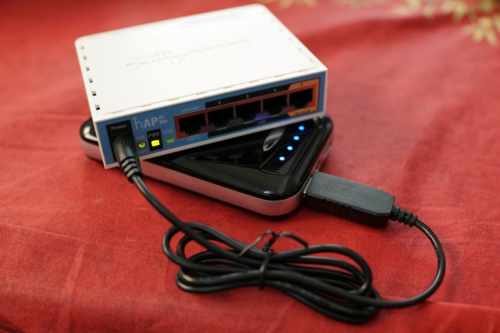
No good on the lake. But remote workers know how to fix this one with a phone charger bank.
Most DC power cables can go to USB easily:
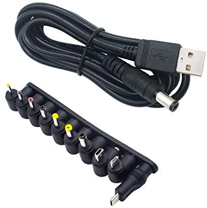
However, we can go one better.

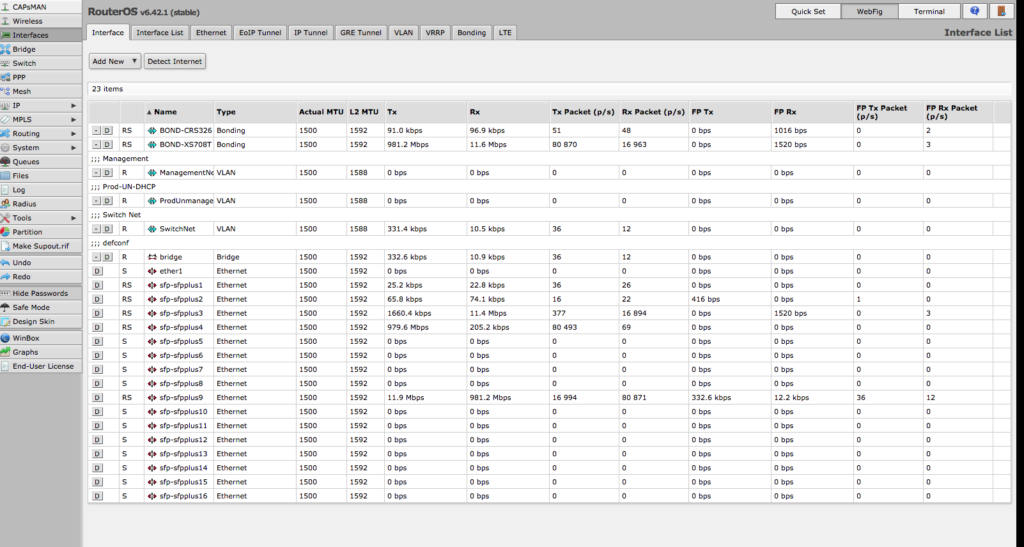
Not only do MikroTik (makers of the amazing RouterOS: https://mikrotik.com/software) have Wifi routers which can use 3G/LTE SIM cards as their upstream Internet connection, but many of their products come with a mini-USB power cable. Connect that to any spare USB phone charger bank, and eh voila, we have a portable Internet/Wifi hotspot for the car, the beach, or anywhere.
You can, of course, use an LTE wifi router from Amazon which has it all built in. Many of them are expensive and none have the control or programmability of RouterOS.
Out of the box will get us everything but the last option. RouterOS is a Linux distro which is unparalleled in how advanced it is.
Giving Our Models A Wifi Brain
There's only really one choice here, and that's Arduino. If you're not familiar with it, Arduino is a $40 open-source microcontroller board for hobbyists which can take on board micro-programs written in Embedded C. You can add a million different little components (e.g. sensors) and program them all differently, like an electrical Lego set.
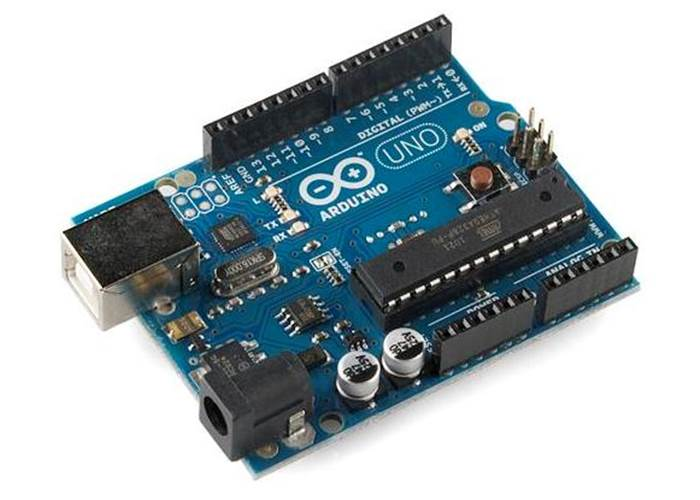
The little board connects to a computer via USB, and its individual pieces are called "shields". Programs/scripts are "uploaded" onto its tiny 4MB ROM memory. It has the power of an alarm clock.
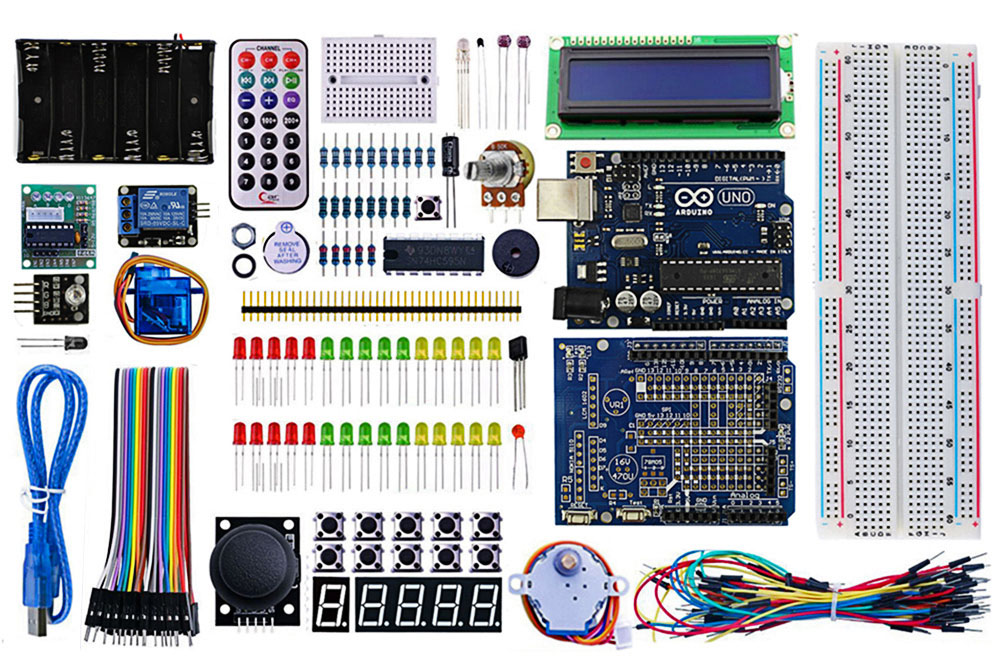
It's worth getting a starter kit for each vehicle.
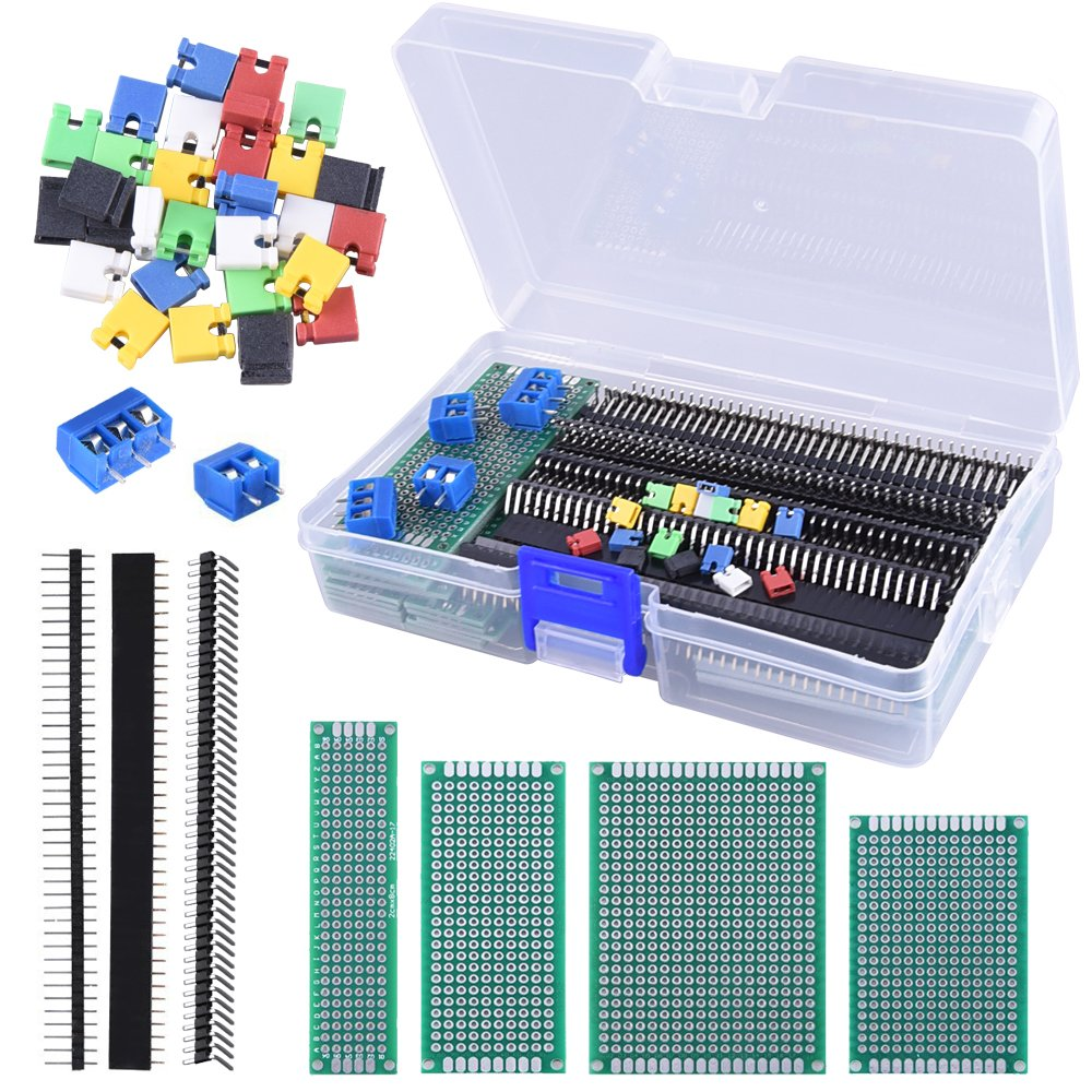
For reason that will become evident later, it's wise to get some extra accessories, such as PCB board space, EL wire, and jumper caps.
Motion: Talking To Our Engines
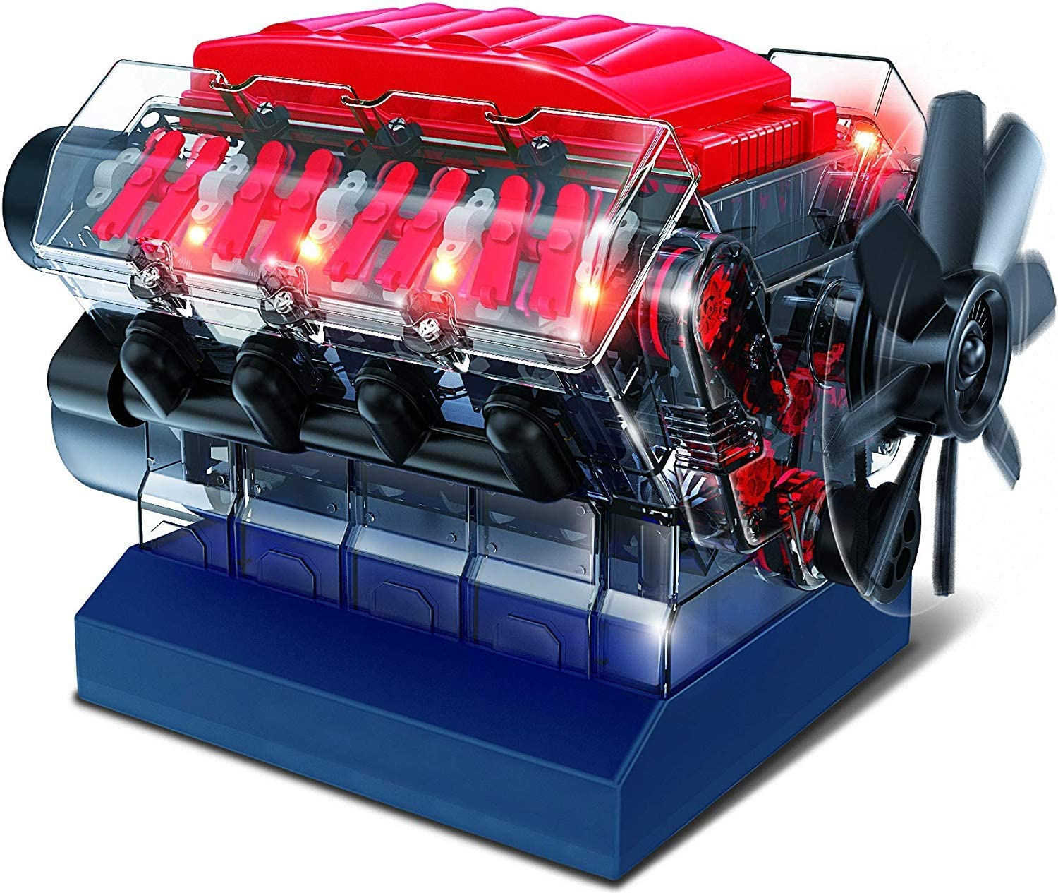
Now, let's not pretend we don't want to build a jet engine here. Of course we do. On Amazon, for instance, you can buy model rockets with launch pads, but you can also get full internal combustion engines:
A toy car has no such glory: it has 2 wheels in the front which go left or right, and 2 wheels in the back which go forward or back. A boat is similar: it has a rudder which moves left or right, and a fan which goes clockwise or counterclockwise. The force at which it does those things is determined by the electrical drive power applied to it.
The Arduino component which talks to motors is called a motor shield.
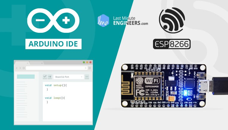
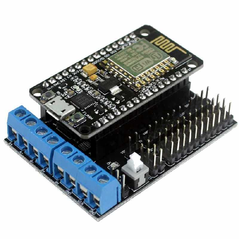
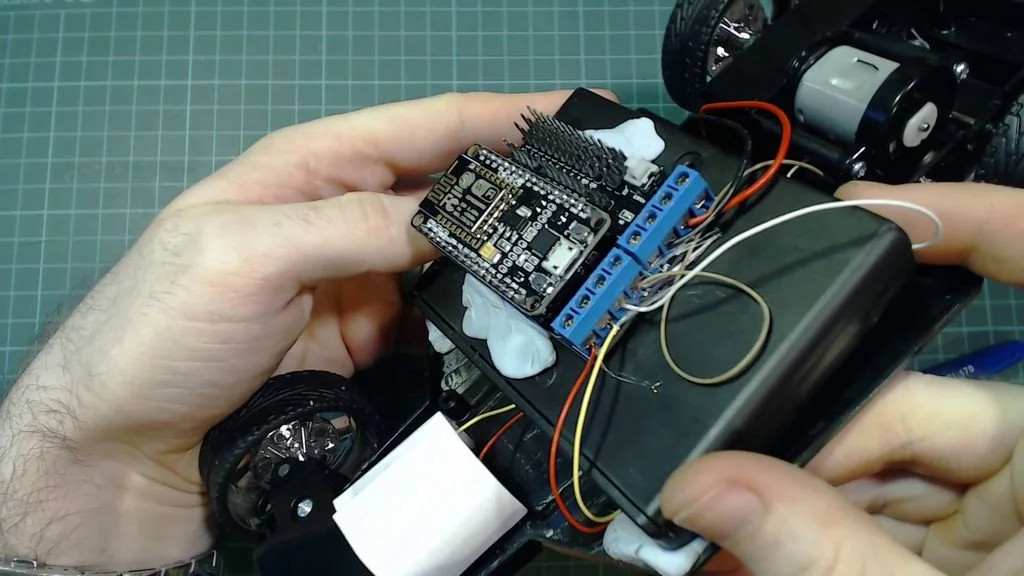
To save time, we can actually get a Wifi module and motor shield in one. One of the most popular Wifi adapters is the NodeMCU ESP8266 Development board.
This is often bundled with the NodeMCU motorshield, such as this: the ESP8266 Development Board NodeMCU Lua WiFi with CP2102 USB and Base/Motor Shield:
There's only one thing left. Each vehicle needs a power supply for microcontroller hardware; when programming it, it draws USB power from your computer.
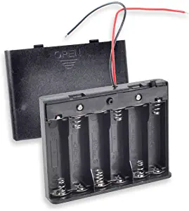
The quick way: get some rechargeable batteries and a storage case which has bare wiring which can feed into the board.
You could also reuse the existing RC battery. For the adventurous, you can also do it with a USB cable and charger pack: https://www.instructables.com/id/Provide-Power-With-an-Old-USB-Cord/
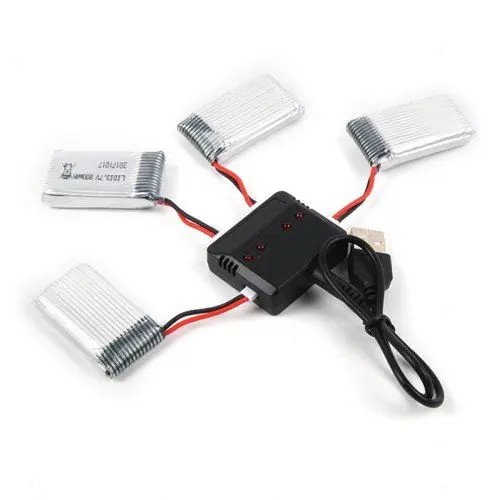
Ideally though, you're going to need something like you find in a modern drone: an on-board battery which charges via a USB cable you can plug into a wall socket with an adapter. Search for any "Li-Po USB battery".
The next step is to open up the RC vehicle, and cut the wires to the existing remote.
Brian gives a great overview here: https://www.instructables.com/id/Simple-WiFi-Controlled-RC-Car/
"Next we need to attach the little jumper block. There is jumper pins between the power button and the screw terminals, you need to connect the two pins labeled VIN and VM. See the second photo for more details.
Now we want to connect up the battery case. Take the red wire from the battery holder and connect it to the VIN screw terminal. (The reason we use the VIN terminal is because the power button switches this on and off). Connect the black wire to either of the GND terminals."
"Next we want to connect the motors to the motor shield. Connect the wires from the steering motor to the screw terminals marked A+ and A-, It doesn't matter which wire goes to the + or the - for the moment (we will come back to this). The drive motor is obviously then connected to the B+ and B- terminals."
There are 8 slots. Think of them as the left/right piece, and the forward/back piece. They both need power. One set of wheels goes into one side with some power, the other set goes in and also needs power. If you don't have enough length, that's where the jumpers and extra EL wire come in - as you'll need them.
The same goes for boats or any other vehicles. If it has a motor (left/right, forward/back), or you add one to turn the rudder/wheel/fan, you can supply power to it from the board.
Once you have 8 of these, now comes the fun part.
Writing The C Script For The Brain
We need to write and download software onto the board to tell it what to do. Each copy will be unique to the microcontroller. At the very least, plug the Arduino into your laptop with the micro USB to give it power.
For clarity, this is what we need to do:
- Main Hardware: - NodeMCU ESP8266 Development Board cp2102
- NodeMCU Motor Shield (L2932)
- Set board in Arduino IDE to "NodeMCU 0.9 ESP-12 Module".
- Set serial output to "Serial" (not "Serial1")
- Make sure you've installed the Silicon Labs CP2012 USB driver
- Make sure you've added ArduinoWebsockets, ArduinoJson, Pusher libraries
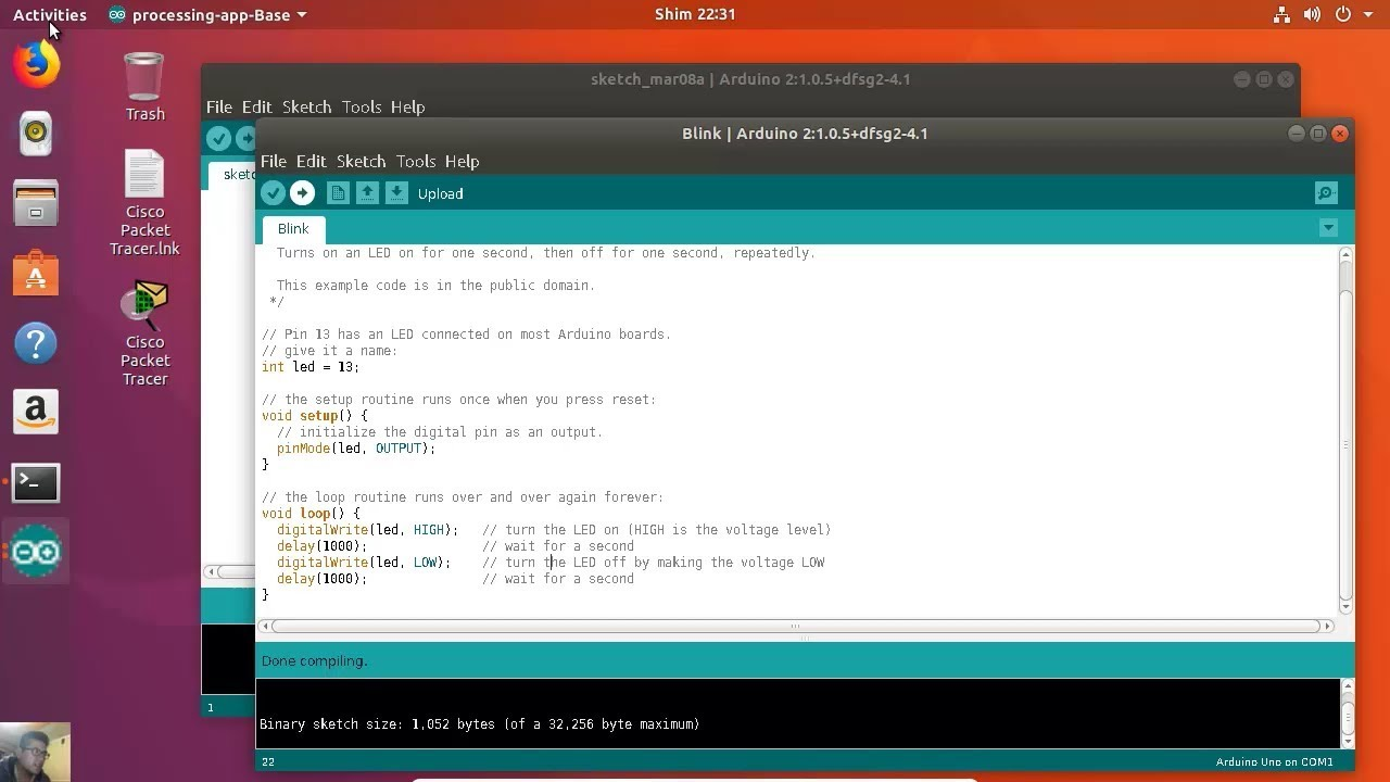
Step A: Download Arduino IDE: https://www.arduino.cc/en/Main/Software. A good overview is here: https://www.instructables.com/lesson/Software-Setup/. This is how it looks on Ubuntu:
Step B: Install the ESP8266 board software into the IDE so it knows how to talk to it: https://github.com/esp8266/Arduino#installing-with-boards-manager
The manual for the motor shield and its settings can be found here: https://legacy.gitbook.com/download/pdf/book/smartarduino/user-mannual-for-esp-12e-motor-shield
Step C: And this is important. Install the Silicon Labs CP2102 USB driver software ("CP210x USB to UART Bridge Virtual COM Port (VCP) drivers") which allows the USB to act like a serial port: https://www.silabs.com/products/development-tools/software/usb-to-uart-bridge-vcp-drivers
This step is annoying and often requires debugging. Set the USB serial monitor Baud rate to 115200.
Understanding How Arduino Scripts Work
Arduino "programs" are written in an embedded form of C. A script is called a sketch. They are small text documents which the IDE compiles into a small binary and "uploads" onto the board via the serial port (USB cable). It can be thought of as a type of "firmware" you create yourself. When we add things like shields, we are performing analog and/or digital writes to the pins on the board.
Learning it is simple: open up the included examples when you're in the IDE.
Every sketch (script) follows the same structure. It is a folder with a .ino file inside with the same name. If our app were called "errmaggherrd", we would have:
errmaggherrd /
errmaggherrd.ino
void setup() {

}

void loop() {


}
The setup() function runs first as the "constructor" (so to speak), and we import libraries and define vars as might be typical in any C code. Then the code inside loop() runs endlessly, forever. When we want to debug something, we can print a newline ("\n") to the "serial" port so it appears in the IDE console.
#include <ArduinoJson.h>

char json_output[256];

void setup() {
  Serial.begin(9600);
  Serial.println("Running startup");
}

void loop() {


}
Then we compile/build, run, and upload to the board. When the board switches on, it executes the sketch.
So we prepare what we need in setup(), then add an endless loop to run. These functions are fixed; we can't add others like init(). It's worth bearing in mind the board has no memory or CPU, so conservative and defensive coding techniques should be use so as not to crash the thing.
The vehicle script in all its glory (brain/brain.ino):
/*******************************************************************
    Main Hardware:
    - NodeMCU ESP8266 Development Board cp2102
    - NodeMCU Motor Shield (L2932)

    IMPORTANT:
    A) Set board in Arduino IDE to "NodeMCU 0.9 ESP-12 Module".
    B) Set serial output to "Serial" (not "Serial1")
    C) Make sure you've installed the Silicon Labs CP2012 USB driver
    D) Make sure you've added ArduinoWebsockets, ArduinoJson, Pusher libraries
 *******************************************************************/

#include <ESP8266WiFi.h>
#include <WiFiClient.h>
#include <ESP8266mDNS.h>

#include <WebSockets.h>
#include <WebSocketsServer.h>
#include <WebSocketsClient.h>
#include <ArduinoJson.h>

// These are the pins used to control the motor shield
// https://www.gitbook.com/book/smartarduino/user-mannual-for-esp-12e-motor-shield/details

#define DRIVE_MOTOR_POWER D2 // PWMA (Motor B), GPIO 4 SPEED
#define DRIVE_MOTOR_DIRECTION D4 // DIRB (Motor B), GPIO 2 DIRECTION

#define STEER_MOTOR_POWER D1 // PWMA (Motor A), GPIO 5 SPEED
#define STEER_MOTOR_DIRECTION D3 // DIRA (Motor A), GPIO 0 DIRECTION

// Set up TCo connector
WiFiClient wifi_client;
MDNSResponder mdns;

// Create the onboard HTTP servers
WebSocketsServer web_socket_server (8080);
WebSocketsClient web_socket_client;

// Sets how fast the car goes
// Can be set between 0 and 1023 (although car probably wont move if values are too low)
int drive_power = 1023;

// Sets what direction the car drives
// If the car is moving backwards when you press the forward button, change this to LOW
uint8_t drive_direction = HIGH;

// Sets how fast the car turns
// Can be set between 0 and 1023 (again, car probably won't steer if the value is too low)
int steering_power = 1023;

// Sets what direction the car steers
// If the car is steering right when you press the left button, change this to LOW
uint8_t steering_direction = HIGH;

// ----------------
// WiFi SSID and Password to connect to
// ----------------
const char* ssid = "mywifinetwork";
const char* password = "crappypassword";

// Outbound network host to connect to
const char* test_host = "google.com";
const uint16_t test_port = 80;

// Set basic HTTP auth for this car
const char* www_username = "boat1";
const char* www_password = "password1";

// The name of the multicast DNS hostname to use for this car
const char* mdns_name = "YACHT1"; // Domain name for the mDNS responder (set differently for each car)
IPAddress ip;

// Pusher details
//ws://ws-us2.pusher.com:80/app/fa8e32fdafa290597c5b?client=esp8266&protocol=5
const char* pusher_channel = "alive";
const char* pusher_app_id = "appid";
const char* pusher_key = "mykey";
const char* pusher_secret = "secretpass";

DynamicJsonDocument life(2048);
JsonObject heartbeat  = life.to<JsonObject>();
char json_output[256];

/******************************************************************************
 SET EVERYTHING UP WHEN SWITCHED ON
*******************************************************************************/
void setup ( void ) {
  Serial.begin (115200);
  Serial.println ("setup ()");

  pinMode (DRIVE_MOTOR_POWER, OUTPUT);
  pinMode (DRIVE_MOTOR_DIRECTION, OUTPUT);
  pinMode (STEER_MOTOR_POWER, OUTPUT);
  pinMode (STEER_MOTOR_DIRECTION, OUTPUT);

  Serial.println ("Connecting to Wifi SSID (" + String (ssid) + ") using password '" + String (password) + "'...");

  WiFi.mode (WIFI_STA);
  WiFi.disconnect ();
  delay (100);

  WiFi.begin (ssid, password);

  // Wait for connection
  while ( WiFi.status() != WL_CONNECTED ) {
    delay (500);
    Serial.print (".");
  }

  Serial.println ("");
  Serial.println("Connected.");

  ip = WiFi.localIP();
  Serial.print("IP address: ");
  Serial.println(WiFi.localIP().toString());

  Serial.println (" ");

  if (MDNS.begin(mdns_name)) {
    mdns.addService("ws", "tcp", 8080);
    Serial.println ("MDNS Responder Started.");
    Serial.println ("DNS host: " + String (mdns_name));
  }

  Serial.println (" ");

  Serial.println ("Attempting to test wifi connection by pinging " + String (test_host) + "...");
  if (!wifi_client.connect(test_host, test_port)) {
    Serial.println("Connection failed.");
  } else {
    Serial.println("Succeeded. We have an outbound internet connection through the Wifi router.");

  }

  Serial.println (" ");

  Serial.println ("Setting up inbound WebSocket server...");
  web_socket_server.begin ();
  web_socket_server.setAuthorization (www_username, www_password);
  web_socket_server.onEvent (receive_ws_event);
  Serial.print("WebSocket server started: ws://");
  Serial.print(WiFi.localIP().toString());
  Serial.println(":8080");

  Serial.println ("Authentication: " + String (www_username) + "/" + String (www_password));
  Serial.println ("Use ws://" + String (www_username) + ":" + String (www_password) + "@" + WiFi.localIP().toString() + ":8080 to connect.");
  Serial.println ("ESP8266 does not support SSL yet. wss:// will not work.");

  Serial.println (" ");

  Serial.print ("Drive power set to ");
  Serial.print (drive_power);
  Serial.println (".");

  Serial.print ("Steering power set to ");
  Serial.print (steering_power);
  Serial.println (".");

  Serial.println (" ");

  Serial.println ("READY.");
  Serial.println ("Available WS commands are: [F]orward | [S]top | [B]ack | [L]eft | [R]ight. Send single plain-text characters only.");
  Serial.println ("Example: To drive forward, send the single text letter 'F'. To go back, send the single text letter 'B'.");
  Serial.println ("Motion smoothness is up to you in the UI (think onTouchStart, onTouchEnd, onMouseUp, onKeyUp etc).");

  Serial.println (" ");

  proof_of_life ();
}

/******************************************************************************
 PROCESS INDIVIDUAL INCOMING COMMANDS
*******************************************************************************/
void forward () {
  Serial.println ("FORWARD");
  analogWrite (DRIVE_MOTOR_POWER, drive_power);
  digitalWrite (DRIVE_MOTOR_DIRECTION, drive_direction);
}

void stop () {
  Serial.println ("STOP");
  analogWrite (DRIVE_MOTOR_POWER, 0);
}

void back () {
  Serial.println ("BACK");
  analogWrite (DRIVE_MOTOR_POWER, drive_power);
  digitalWrite (DRIVE_MOTOR_DIRECTION, !drive_direction);
}

void left () {
  Serial.println("LEFT");
  analogWrite (STEER_MOTOR_POWER, steering_power);
  digitalWrite (STEER_MOTOR_DIRECTION, !steering_direction);
}

void right () {
  Serial.println("RIGHT");
  analogWrite (STEER_MOTOR_POWER, steering_power);
  digitalWrite (STEER_MOTOR_DIRECTION, steering_direction);
}

/******************************************************************************
 RECEIVE COMMANDS FROM INBOUND WEBSOCKET CONNECTION
*******************************************************************************/
void receive_ws_event (uint8_t num, WStype_t type, uint8_t * payload, size_t length) {
  //Serial.println ("receive_ws_event ()");
  IPAddress client_ip = web_socket_server.remoteIP(num);

  switch ( type ) {
    case WStype_CONNECTED:
      char shake [50];
      sprintf(shake, "Hello %d.%d.%d.%d.\r\n You are client %u.", client_ip[0], client_ip[1], client_ip[2], client_ip[3], num);
      Serial.printf("[%u] Connected from %d.%d.%d.%d url: %s\r\n", num, client_ip[0], client_ip[1], client_ip[2], client_ip[3], payload);
      web_socket_server.sendTXT(num, shake); // client to send to, message, string length
    break;

    case WStype_DISCONNECTED:
      Serial.printf("[%u] Disconnected!\r\n", num);
    break;

    case WStype_BIN:
      // do nothing
    break;

    case WStype_TEXT:

      char received [20];

        if ( length > 1 ) {
          Serial.println ("Payload is more than 1 character. Ignoring.");
          return;
        }

        // this loops through each letter in the string sent over the socket. The word 'code' will iterate 4 times - c, o, d, e
       for ( int i = 0; i < length; i++ ) {
         Serial.print((char) payload[i]);
         Serial.println();

         sprintf(received, "%d: %c", millis(), payload[i]);

         web_socket_server.sendTXT (num, received); // client to send to, message, string length

         switch ((char) payload[i]) {
           case 'F': // 70
            forward ();
           break;

           case 'S': // 83
            stop ();
           break;

           case 'B': // 66
            back ();
           break;

           case 'L': // 76
            left ();
           break;

           case 'R': // 82
            right ();
           break;

           default:
            Serial.println ("Unrecognised command.");
           break;
         }
       }

    break;
  }

}

String ip_string (IPAddress ip) {
  String s="";
  for (int i=0; i<4; i++) {
    s += i  ? "." + String(ip[i]) : String(ip[i]);
  }
  return s;
}

/******************************************************************************
 ANNOUNCE VEHICLE IS ALIVE ON THE NETWORK EVERY (X) SECONDS
*******************************************************************************/
void proof_of_life () {

  heartbeat["mdns"]    = mdns_name;
  heartbeat["ip"]      = wifi_client.localIP().toString();
  heartbeat["uptime"]  = millis();

  serializeJson (heartbeat, json_output);

  Serial.print ("proof_of_life (): ");
  Serial.println (json_output);

}

/******************************************************************************
 RUN ALL THE THINGS FOREVAAAH WHILE POWER IS ON
*******************************************************************************/
void loop ( void ) {

  web_socket_server.loop();

  if ( Serial.available() > 0 ) {
    char c[] = {(char)Serial.read()};
    web_socket_server.broadcastTXT (c, sizeof(c));
  }

  const unsigned long mins = 1 * 30 * 1000UL;
  static unsigned long last_broadcast = 0 - mins;
  unsigned long now = millis();

   if (now - last_broadcast >= mins) {
      last_broadcast += mins;
      proof_of_life ();
   }

}
A Walkthrough of the Brain Sketch For Each Vehicle
The theory of what we are doing here is relatively simple. In a production grade system we'd remove everything which isn't strictly necessary, for example, the serial debugging.
The theory is the vehicles should all connect to the same Wifi network. Each vehicle should offer a Websocket server on which it can be sent commands. You can do this with a normal HTTP server, but it's slower and needs more work.
Before anything else, we're importing:
- The ESP8226 Wifi and mDNS controls
- The standard Wifi client
- A Websockets library
- A JSON library
These need to be installed in the IDE first. For an example of how to do this:
What's happening in the setup:
- Connect to the serial interface (USB)
- Set the motor pins to output power
- Connect to a password-protected Wifi network (mywifinetwork) to get an IP address via DHCP
- Broadcast a new vehicle hostname via multicast DNS (YACHT1)
- Test connection by doing n HTTP request to google.com
- Attempt to announce presence by connecting to Pusher
- Launch a Websocket server on port 8080 which is password-protected (boat1/password1, need to be set for each board)
- Set the amount of power to send to the motors
- Start sending a "proof of life" every second to say it's alive and ready to race
All the info debugs into the IDE console for checking. It turns out most of this has a tendency to overload the little Arduino board.
Now, once that's up, and the vehicle has announced it's on the network and ready to receive commands, we're on to the loop() logic. What's going on here is far simpler:
- Receive plain text web socket messages (1 character long) and send to receive_ws_event()
- Broadcast "proof of life" every X seconds as a JSON payload
For testing, we can connect to ws://192.168.0.250:8080 (if the car has IP 250) with a basic socket client like so: https://chrome.google.com/webstore/detail/simple-websocket-client/pfdhoblngboilpfeibdedpjgfnlcodoo
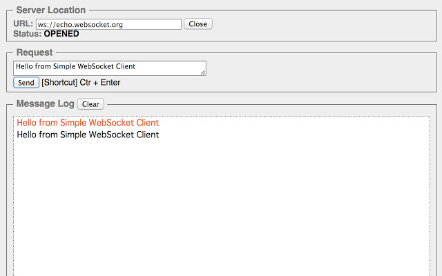
We send 1-character-long commands to keep it fast.
         switch ((char) payload[i]) {
           case 'F': // 70
            forward ();
           break;

void forward () {
  Serial.println ("FORWARD");
  analogWrite (DRIVE_MOTOR_POWER, drive_power);
  digitalWrite (DRIVE_MOTOR_DIRECTION, drive_direction);
}

void stop () {
  Serial.println ("STOP");
  analogWrite (DRIVE_MOTOR_POWER, 0);
}
We have to take account of the board rebooting, power failing, or the connection dying. But something else is more important: the drive power. In the command above, when we hit forward, we are "writing" power from the battery to the motor but not stopping the writing, i.e. keeping it going. The more power, the faster the wheel or fan spins.
We need a stop function to take the power back to zero or it will just carry on until the battery wears out. Writing to the pin when using a motor can be seen as a binary operation - write all power at once as an "on" state, or stop routing power as an "off" state. We are setting the motor on/off via the power being supplied or not.
At this point, it's trivial to put together a UI: a browser can load an application whicb detects the "alive" vehicles from their "proof of life" pings, and display a list of their IPs. When connecting, a driver needs to supply a user/pass (so the other drivers can't control each other's cars).
Any modern browser can directly connect to the Websocket server on the vehicle to send it commands to increase/decrease the drive power to the motor. Each vehicle can send any reports it likes via HTTPS (speed, location, battery power, etc).
When You Need Even More Cowbell
You could add anything onto the Arduino board - like a GPS chip which communicate its position to the incoming drone wanting to land: https://www.instructables.com/id/Connecting-GPS-module-to-Arduino/
Or perhaps, add a rocket launch pad onto your aircraft carrier to shoot it down: https://www.instructables.com/id/Rocket-Launch-Pad/
The most obvious candidate is, of course, a live action First-Person-View (FPV) camera. The most important thing to know is Arduino can't cope with video. It's too CPU intensive. If you really want to go with streaming compressed video via a webcam, you need something with more power like a Raspberry Pi.
The most practical way to do it is to mount a set of creepy battery-powered Wifi spy cams onto the vehicles (which connect to the same wifi network) and stream their output to an RTMP/RTSP endpoint which has the power to mux the signals into combined "squares" for display.
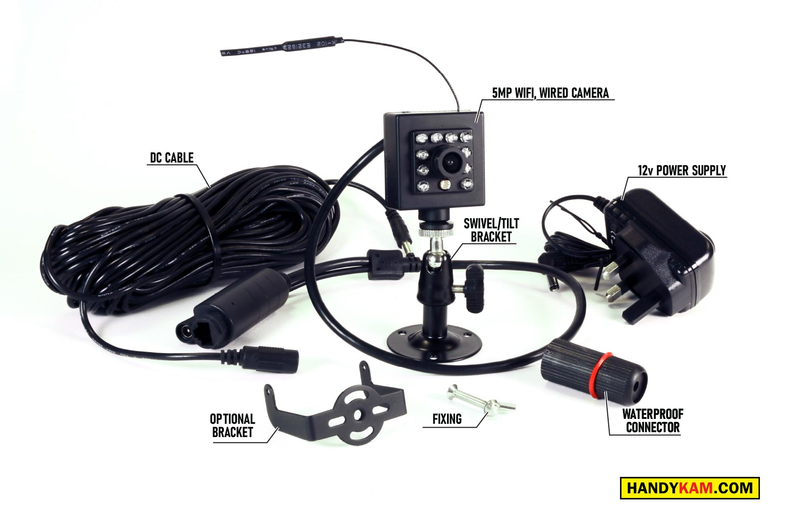
- https://handykam.com/product/wifi-mini-cam-5mp/
- https://www.tradees.com/detail-wsel/hd-1080p-Magnetic-WiFi-mini-Camera-with-built-in-rechargeable-battery-night-vision_88137/
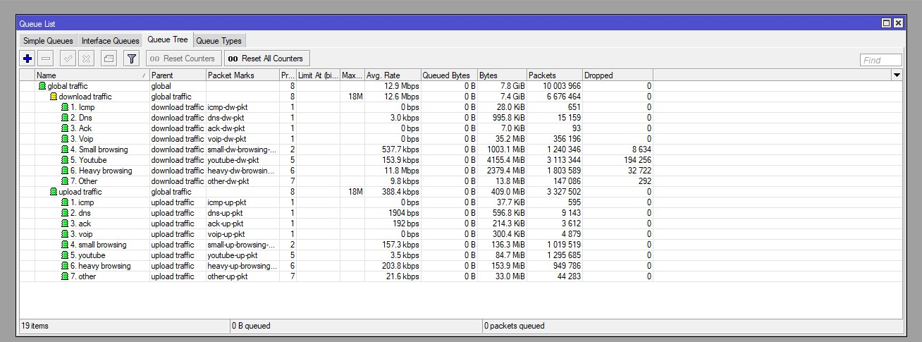
How do you stop the cameras eating the Wifi bandwidth and interfering with the control bands for the cars/boats?
Well that's why you want to go with RouterOS and Mikrotik router, rather than a 4G Netgear SIM card router. Because it gives the ability to fine tune Quality of Service (QoS) and even set them each on different VLANS or Wifi SSIDs. If you were mad enough, you could even make people sign up through a captive portal hotspot page, or enforce it all happen on a VPN.
Let's face it though. There's only one reason for any of this when it comes to your inner six year-old: creating weapons and going to war.